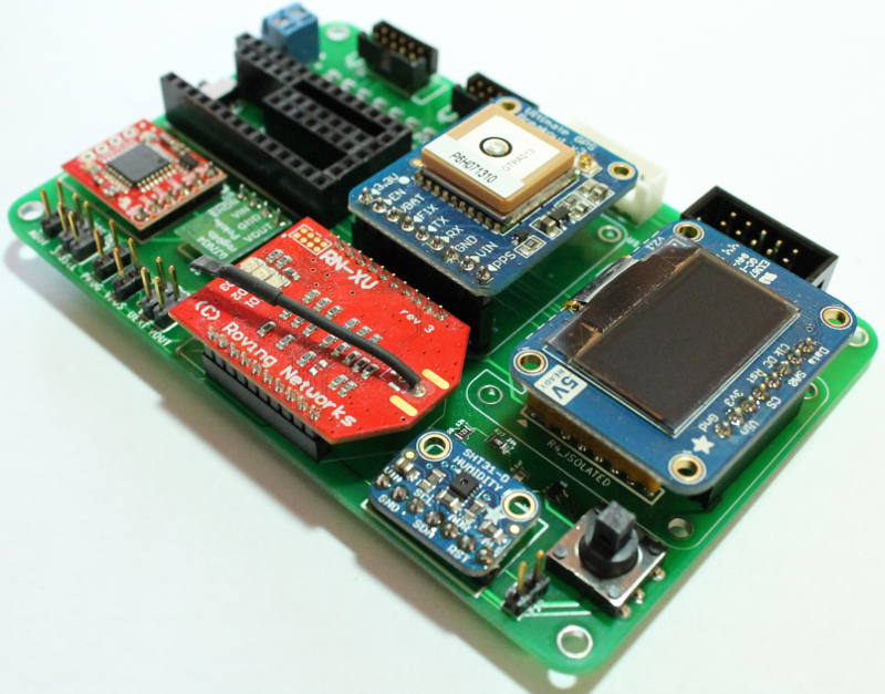
Placing GPS, XBEE and display
In this step, place the following three components into the female headers which were placed earlier. These components are not soldered, as the pins on the components are instead pushed into the headers.
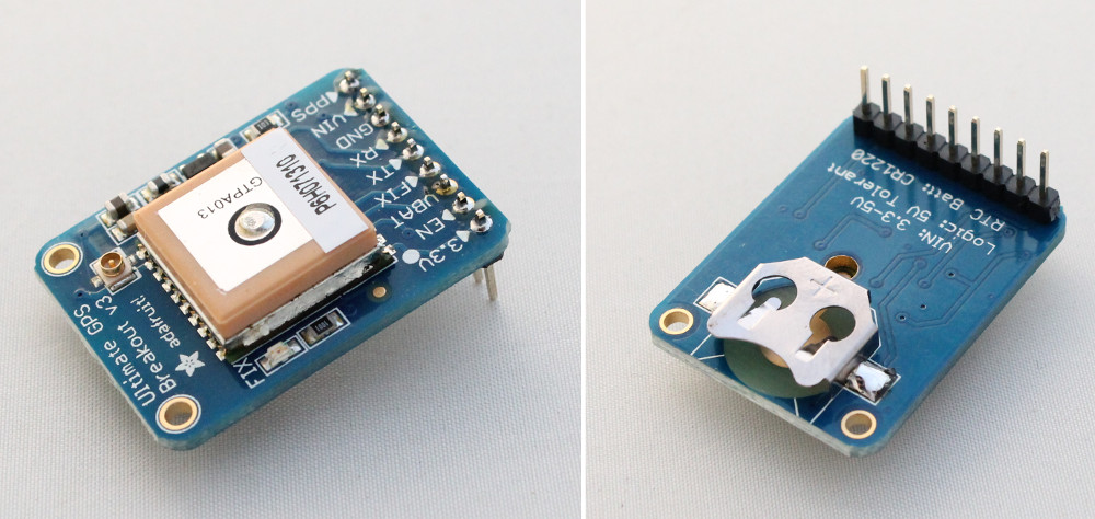
Adafruit Ultimate GPS Breakout
Adafruit GPS Breakout board comes with a 9-pin array. Solder this onto the breakout board as shown in the images below.
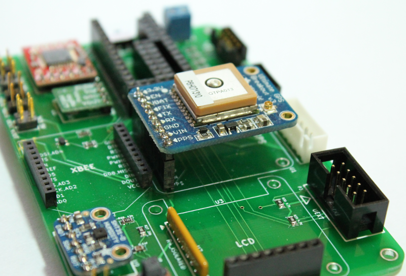
Insert the GPS board into the 9-position female header as shown in the image below.
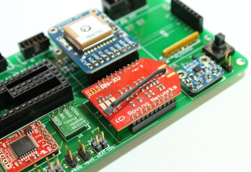
XBEE/WiFly wireless communication module
Insert the XBEE RF module or Sparkfun RN-XV WiFly into the sockets as shown in the image below.
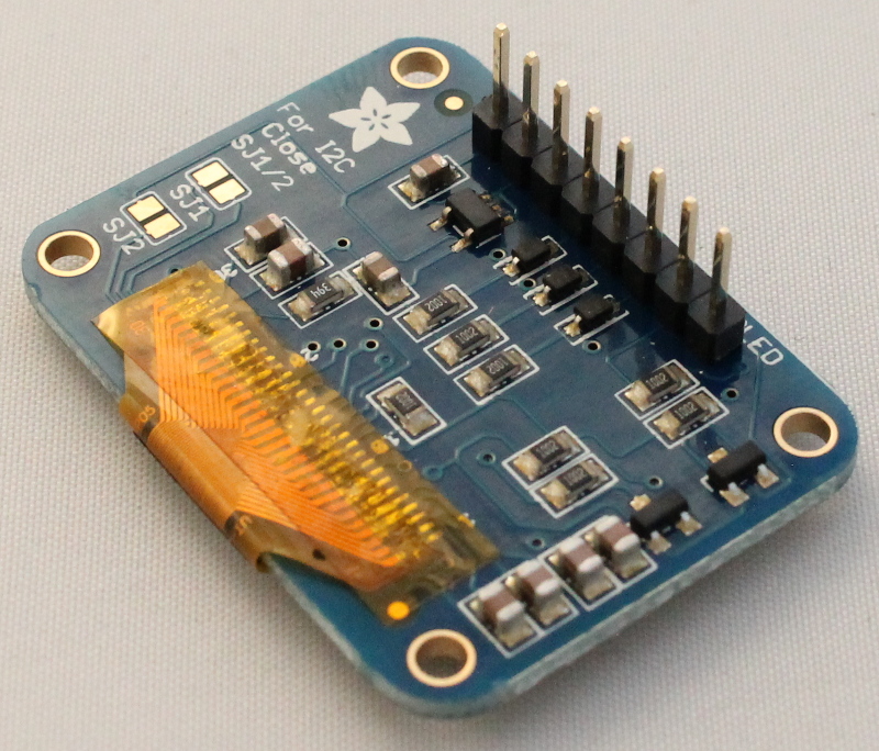
Adafruit OLED graphic display
The Adafruit graphic display comes with an 8-pin array. Solder this onto the board as shown in the image below and insert the LCD display into the 8-position female header.