Solder Pin Headers
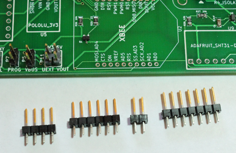
- Take the same breakaway header from the previous step and break off a 4-pin, 6-pin header, 2-pin and 7-pin header.

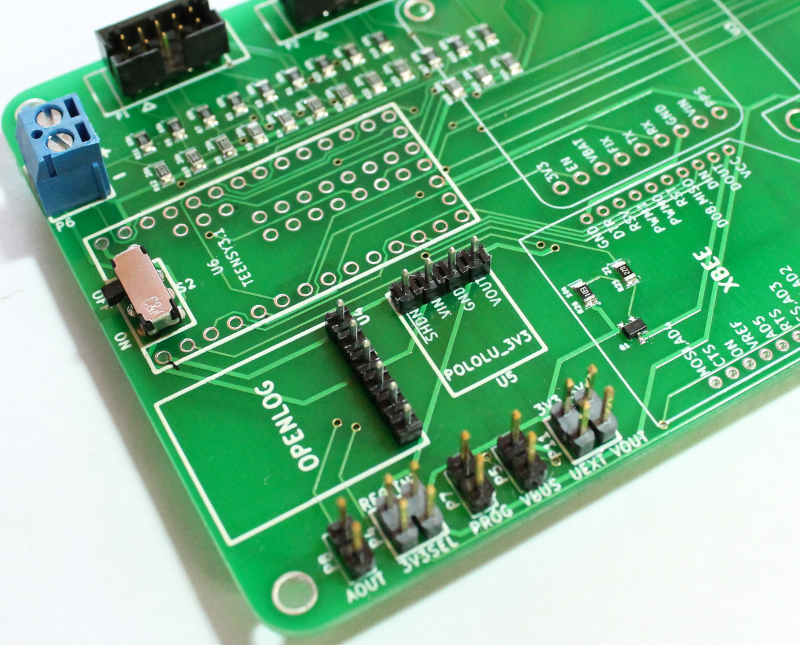
- Solder the 6-pin and 4-pin into positions U4 and U5 as shown in the image below. Solder with the shorter pin side facing up. These pin headers will be used to connect the OpenLog SD card data logger and Pololu 3V3 optional power regulator later in the instructions.

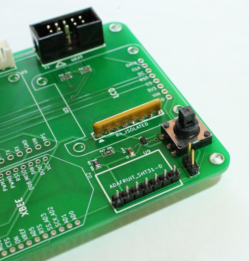
- Solder the 7-pin header into position U9 as shown in the image below. Solder with the shorter pin side facing up. This pin header will be used to connect the Adafruit temp/humidity sensor later in the instructions.
- Solder the 2-pin header into position P10. For this header, solder with the longer pin side facing up. This pin header can be used with a jumper to change the I2C address of the Adafruit temp/humidity sensor in the event of a conflict with an optional device on the UEXT header.

