GPS, LCD and XBEE Headers
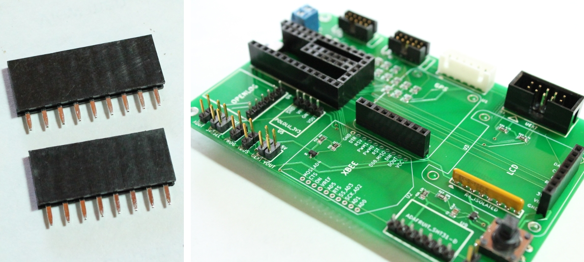
This step also involves soldering the same type of female headers onto the board.
- Solder a 9-pos feamle header into U1
- Solder a 8-pos feamle header into U3
- These female headers will be used to connect the Adafruit Ultimate GPS Breakout, Adafruit OLED graphic display later in the instructions.

- Take the two 10-position XBEE headers. These are shorter headers than the ones used in the previous steps.
- Solder these into the board at position U2
- These female headers will be used to connect the XBEE RF module or Sparkfun RN-XV WiFly later in the instructions.

